Valves - Directional Controls - Check Valve

CV10-28

CHECK VALVE WITH THERMAL RELIEF

Overview

Description

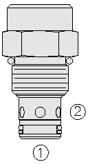
CV10-28 is a screw-in, cartridge-style hydraulic check valve for use as a blocking or load-holding device. The cartridge incorporates a low flow thermal relief valve intended to prevent cylinder damage resulting from temperature-induced pressure intensification.

NOTE: The thermal relief feature is not intended for use in dynamic pressure limiting applications.

Operation

The CV10-28 allows flow from port 1 to port 2, while blocking oil flow in the opposite direction. If the pressure at port 2 exceeds the thermal relief setting, a small amount of oil will be allowed to pass from port 2 to port 1, preventing cylinder damage from pressure intensification.

Features

  • Hardened seat for long life and low leakage.
  • Industry-common cavity.
Pressure Ratings
Pressure rating:
  • 241 bar (3500 psi)
Proof pressure:
  • 390 bar (5700 psi)
Flow Ratings
Flow rating:
  • 45 lpm (12 gpm)
Maximum internal leakage:
  • 0.25 ml/min (5 drops/min) At 241 bar (3500 psi)
Temperature Ratings
Operating fluid temperature:
  • -40 to 100 °C (-40 to 212 °F) With buna N seals
  • -26 to 204 °C (-15 to 400 °F) With viton seals
  • -54 to 107 °C (-65 to 225 °F) With polyurethane seals
Storage temperature:
  • -40 to 70 °C (-40 to 160 °F)
Ambient temperature:
  • -40 to 70 °C (-40 to 160 °F)
Fluids:
  • Mineral based or synthetic hydraulic fluid with lubricating properties
Fluid viscosity range:
  • 7.4 to 420 cSt
Maximum operating contamination level:
  • 20/18/14 per ISO 4406
Unit weight:
  • 0.13 kg (0.28 lb)
Internal wetted surface area:
  • 287 cm² (17.5 in²)
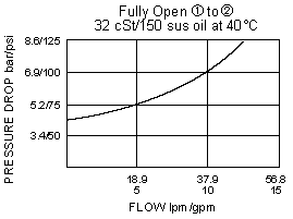
CV10-28_Perf_Chrt(2022-02-24)
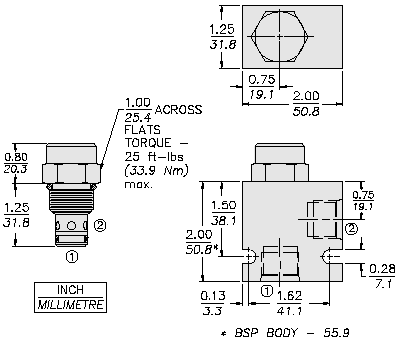
CV10-28_Dim_Dwg(2022-02-24)
Cavity:
Cartridge installation torque:
  • 32.6 to 35.4 N-m (24 to 26 ft-lb)
Orientation restriction:
  • None
Seal kit:
  • SK10-2X-T X = seal option
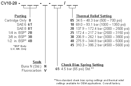
CV10-28_Order(2022-02-24)

Model Options

CV10-28-H-J-R/S
H Line Body
CODE
DESCRIPTION
0
No Body
6T
Aluminum SAE 6
8T
Aluminum SAE 8
6TD
Ductile Iron SAE 6
8TD
Ductile Iron SAE 8
2B
Aluminum BSPP 1/4" (2)
3B
Aluminum BSPP 3/8" (3)
4B
Aluminum BSPP 1/2" (4)
4BD
Ductile Iron BSPP 1/2" (4)
J Seal
CODE
DESCRIPTION
N
Buna-N
V
Fluorocarbon
P
Polyurethane
U
PPDI Urethane
R Spring
CODE
DESCRIPTION
65
65 psi Bias Spring
S Thermal Relief Setting
CODE
DESCRIPTION
5
500 psi Thermal Relief
10
1000 psi Thermal Relief
20
2000 psi Thermal Relief
25
2500 psi Thermal Relief
30
3000 psi Thermal Relief
40
4000 psi Thermal Relief
45
4500 psi Thermal Relief